
Explore this service in pictures

Technical specifications
| Materials | MDF, wood-based sheets, acrylic, other sheet materials assessed for suitability |
|---|---|
| Working area | Routers: 200 × 400 cm and 210 × 280 cm; laser for suitable materials: 140 × 100 cm. |
| Thickness | Confirmed according to material, design and intended use. |
| Tolerance | ±0.1 mm target tolerance; confirmed for each job. |
Define the model's purpose before production
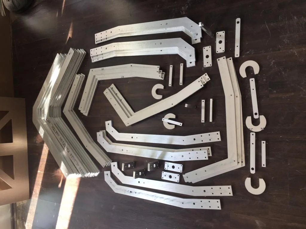
For mould and scale model cutting, what the part represents and how it will be used are key considerations. A presentation model, trial assembly component, template and production mould have different requirements. At Modoko CNC Kesim Cutting Centre, we assess drawings, materials and intended use together. When sending your file to our Istanbul Dudullu workshop, identify joints and the features you want to verify as well as overall dimensions. This helps define the right production scope.
Machining only the outer shape of a mould is different from supplying a finished mould suitable for a specific production process. Explain the material, operating conditions and subsequent operations. Share the technical requirements of the team responsible for that process. Cutting alone does not confirm that the design or material is suitable for it. Clearly specify the cutting, surface machining and delivery condition expected from us. Let’s also discuss samples and inspection stages as part of the quote.
The relationship between scale and actual dimensions
Specify the scale clearly for model-making work. State whether the drawing uses full-size product dimensions or the dimensions of the model to be produced. Sheet thickness, joint slots and fine details must be reassessed after scaling. Reducing the overall dimensions of a structure does not automatically make every joint compatible with the material. Provide the target model width and length separately for verification, so the dimensions displayed when opening the file can be checked against an independent reference.
In a presentation model, visible details and structural or connecting details may have different priorities. Explain which parts are purely visual and which support other components. Decide during design how fine components will be represented at a reduced scale. Send an overall layout and individual part drawings rather than a single screenshot. Considering assembly order helps identify joints that will become inaccessible after cutting.
Material and production method
MDF, wood-based sheets, acrylic and other suitable materials are assessed according to their intended use. Provide the exact sheet type, actual thickness and supplier details. A material suitable for a presentation model is not necessarily suitable for a production mould. State the technical requirements of the intended application separately. Our MDF CNC cutting service explains the relationship between sheet material and surface machining, while our acrylic cutting page covers requests for clear or coloured parts.
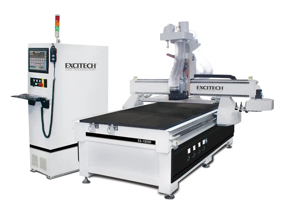
Modoko CNC Kesim has three-axis routers with working areas of 200 × 400 cm (Exitech) and 210 × 280 cm (Mutlucam). For suitable materials, we also assess laser cutting on our Xenon 140 × 100 cm, 200 W CO2 laser. The method is selected according to geometry and material. Table area must be considered alongside workholding and nesting allowances. If a large model will be divided into sections, show the split locations in the design. Agree which team will join the sections at the quotation stage.
Joints and connections
Send the files for mating parts together. Slots, tabs, holes and corresponding edges must use the same dimensional system. Actual material thickness is important. Specify whether the assembly needs clearance, a tight fit or adhesive. Giving a tolerance for one part while leaving its mating part undefined is insufficient. The general ±0.1 mm target tolerance is confirmed for each job; the fit of the full assembly is assessed against the mating components and agreed acceptance criteria.
Choose a sample part that represents the most critical joint. Producing only the largest panel may not demonstrate whether a small interlocking feature fits. Define the outer dimensions, hole positions or joint clearance to be checked on the first sample. If another team prepares the mating part, ensure both teams use the same dimensional information and revision. Report any changes in thickness or geometry after approval. If the conditions represented by the sample change, the decision to proceed with batch production must be reassessed.
Two-dimensional drawings and three-dimensional models
For parts cut from flat sheets, define outer contours and internal cut-outs in a DXF or DWG file. Show pockets, grooves and operations at different depths on separate layers with notes. A three-dimensional surface needs a model containing height information. Identify the front, back and machining faces. A model photo or PDF view helps with assessment and serves as a reference alongside dimensioned production data. Clearly identify which information governs production.
Our DXF file preparation guide explains scale and line checks. For raised surfaces, read the 3D relief file preparation guide. Separate construction lines that must not be cut and remove obsolete alternatives from the production files. If a part has several views, specify which contains the cutting boundary. Identify any model editing or redrawing required separately; this preparation may differ in scope from machining an existing file.
Part codes and assembly order
Assign a code to every component in a multi-part model. Collect codes, quantities, material, thickness and any orientation information in one list. Distinguish left- and right-hand parts, mirrored versions and variants using different faces. Check that the same code does not refer to different parts in separate files. Show where each code is used on the overall layout. If parts should be sorted into sets after cutting, match the packing plan to this list. Consistent coding makes it easier to find the correct component during assembly.
Identify affected part codes in writing when changing a design. If a joint position changes, the mating part must also be updated. Mixing old and new versions in the same folder makes production tracking difficult. Mark the current file with a date or version number. The list approved for production must match the installation team's list. Update the order list when batch quantities change, even if the geometry stays the same. Discuss the impact of any changes made after the first part separately.
Factors determining price and lead time
Mould and model cutting prices take account of the number of different designs, material, total quantity, cutting details and surface machining scope. A ready, checked file requires different preparation from a job needing design adjustments. Specify samples, sorting into sets and special packaging in the quotation request. Our contract CNC cutting page explains the general workflow, while our pricing page explains how to compare scopes of work. Requesting a quotation from your own drawing rather than relying on a fixed figure helps establish your actual requirements.
The delivery plan treats file approval, material sourcing, production, sample assessment and transport separately. Include the time needed for model assembly or final surface treatment in your own schedule. Our completed work gallery shows various geometries and component applications. Collection from the Dudullu workshop in Istanbul and shipping throughout Türkiye are discussed for each job. Send your design, parts list and intended use through the quotation form so we can clarify the scope of your mould or model project together.
Frequently asked questions
What should I specify in a scale model file?
State the scale and actual dimensions of the model to be produced. Sheet thickness and joints are checked against these dimensions.
Is a machined mould suitable for every process?
No. The technical requirements of the intended process need separate assessment. Clearly specify the cutting scope and material requirements.
Is installation included?
Cutting, separating parts, finishing and assembly are discussed as separate scopes of work.