
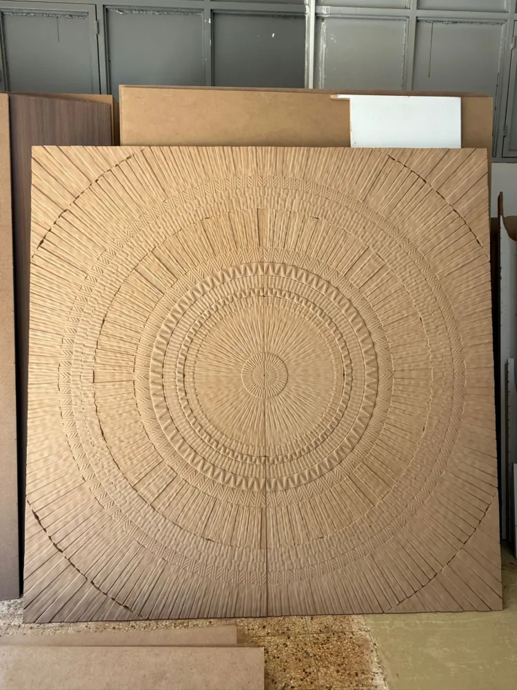
Start by describing the part to be produced
Preparing a file for three-dimensional relief work begins with more than finding a model. First describe how the part will be used. A decorative wall panel, cabinet door and small component within a composition have different fixing and dimensional requirements. Before sending the model, collect the target width, length, overall thickness and quantity. Explain which face will be visible, whether another component will sit behind it and how it will be installed.
These details help distinguish visual expectations from production requirements. For example, lighting may make relief depth look greater in a reference photograph than it really is. The same pattern may appear flatter with different colours or lighting. Sending a photograph you like is useful, but do not leave dimension and depth decisions to the photograph alone. At Modoko CNC Kesim, relief carving requests are assessed using the model, material and intended use together.
The difference between a visual reference and a production model
A photo or drawing conveys how you want the design to look. A production model defines the actual surface shape and heights. A single front view may not reveal the correct depth of every recess and raised feature. Side views, close-ups or photos under different lighting can clarify the design intent. Still, explain why you are sending these references: to check an existing model or to request a new one.
If you only have a photograph, say so rather than describing it as a production-ready file. Explaining that model preparation is needed helps define the scope and lead time correctly. Turning an image into a relief product may require separate design work. The file should also be yours or come from a source you have permission to use. Check the necessary usage permission before using someone else’s model for commercial production.
Checking units and scale in an STL file
STL is our preferred file format for three-dimensional machining requests. State the model's target dimensions separately when sending the file; do not rely solely on it looking correct in the software. Use the same unit for width, length and height. For example, interpreting a dimension given in centimetres as millimetres in the model produces a very different part. Including a screenshot showing the dimensions helps with the initial check.
When resizing a model, specify which axes change. You may want to increase width and length proportionally while keeping relief height unchanged. Scaling all axes together changes both the pattern's extent and its depth. These approaches produce different results. If you send a photograph of a sample made at the old size alongside a resized file, explain the difference. Clearly state the dimensions of the production version in the file name or accompanying note.
Front face, rear face and relief orientation
Specifying which side of the relief will be machined is a simple but necessary step. Some models may be rotated or saved with different coordinate orientations. Include a front-view image and orientation notes. You can mark high points to distinguish raised areas from recesses. If you want a negative version of the model, explicitly state this, as it differs from a standard decorative surface request.
Also specify the material thickness that must remain at the back and any areas that must not be machined. Hinge or connection areas on cabinet doors and hanging points on wall panels may form part of the design. Mounting holes or rear-face operations may need a separate drawing; do not assume the front-face model defines them automatically. Total part thickness and relief height are different measurements. Specify both separately to avoid misinterpretation.
Inspect the model's surface
Where possible, reopen the exported file and check it. Look for unexpected surface gaps, disconnected parts or small components located far from the model. A model appearing on screen does not by itself prove that it can be manufactured. In a multi-part file, identify the components to be machined. Separating construction drawings and reference-only objects from the production model makes the file easier to understand.
The model's level of detail should adequately represent the visible surface. An overly coarse export may make surfaces that should be smooth appear faceted. Conversely, unnecessarily increasing file size does not by itself guarantee a better production result. Describe the required surface appearance and the dimensions used to prepare the file. If you notice a problem, flag it in a note so we can agree who will correct it and how the correction will be approved before production.
Assess fine details and tool access
Not every three-dimensional shape can be treated as a relief machined from one direction. Models may contain undercuts or surfaces inaccessible from above. Machining direction and tool access on Modoko CNC Kesim’s 3-axis routers are assessed from the file. Mark such areas in your design. A feature existing on a reference product does not mean it can be reproduced by the same method in your chosen material and size.
Identify the important features in narrow gaps, thin projections and sharp surface transitions. Some areas can become very narrow when a model is reduced in size; do not assume scaling preserves every detail equally. Distinguishing the surfaces that define the overall design from small decorative details makes possible adjustments easier to discuss. If a change is proposed, review the new version before approving production and record the approved file name.
Material and final surface treatments
Choosing between MDF and wood involves more than colour. Consider material structure, thickness, the visible face and subsequent processes together. Grain direction may matter in a wood design, while a painted MDF panel may require a different finish. State who will supply the material when requesting a quotation. If you supply it, provide its actual dimensions and current condition. Our MDF material guide and solid wood and edge-glued panel information can help with preparation.
Treat CNC machining, sanding, painting and assembly as separate stages. Allow for the effect of surface finishing when comparing a photo of an unfinished machined panel with a painted installation. If painting or coating is planned, check the finishing team’s requirements in advance. Very deep or closely spaced relief details can affect later operations. Confirm in writing which stages the cutting quote includes and clearly describe the finished product you expect.
Deciding on sections and samples for large panels
For large wall compositions, transport and installation constraints matter as much as table size. Check how the part will enter the installation area. If the job is divided into sections, prepare an overall view showing joints and pattern continuity. Number each part and clearly show the front face, upward orientation and assembly order. Do not assume different panels from the same design are interchangeable. Specify joint dimensions and requirements separately.
Requesting a sample before batch production can be useful. Clarify what it will verify: material choice, relief depth, surface detail and colour are separate matters. A small section sample does not demonstrate the handling or installation behaviour of a full panel. A trial in raw material does not by itself represent the final painted appearance. If changes follow sample approval, allow time to check the revised file and plan the schedule accordingly.
Final check before submission
Prepare your file, target dimensions, material type, thickness and quantity together. Mark critical details and areas that must remain unmachined. Name reference photographs separately from production files. Do not include old versions in the same archive; clearly identify the final model to be used. Add your target delivery date and preferred delivery method. Explore our completed relief carvings to find a similar surface reference. When ready, send your file through the quotation form so we can clarify uncertain details before production.
Frequently asked questions
Does an STL file guarantee the measurement unit?
An STL file may not reliably preserve measurement units. State the unit used, such as millimetres, and the target width and length separately.
Is a screenshot enough for production?
A screenshot conveys your expectations; machining also requires a suitable model file and dimensions.